Internetworking Basics

  •  

     Networking Media


    Cables, Connectors and Other Media

    These notes guide you through the understanding of the networking media.

    Introduction
    Coaxial Cable
    UTP Cable
    STP Cable
    Fiber Optic Cable
    Wireless Media
    Summary


    Introduction

    On completion of these notes you should be

    • Describe coaxial cables, connectors and their use on LANs
    • Describe UTP cables, connectors and their use on LANs
    • Describe STP cables, connectors and their use on LANs
    • Describe fiber-optic cables, connectors and their use
    • Describe wireless networks, their operation, devices and security issues
     

    Coaxial Cable

    Coaxial cable is composed of a central conductor, insulation, mesh shielding that acts as a second wire and also protects the cable from noise and an outer plastic jacket. You may be familiar with this type of cable since it is commonly used in homes for cable television and cable Internet connections.


    Speed: 10 Mbps
      

    Maximum Distance:  
          500m Thicknet
          185m Thinnet
      

    Cost: expensive


    Two types of coaxial cable can be used on LANs, Thicknet and Thinnet.

    Thicknet was the cable of choice on the first Ethernet LAN built in the 60's. One of its main advantages is that it can be run for long distances without repeaters, up to 500 metres. It is also fairly resistance to noise interference. Cable with a diameter of 1cm were used as backbone cables on networks. One of the problems with this type of cable though is its rigidity. This makes it difficult to install and the more difficult a cable is to install, the more expensive an installation becomes.

    Thinnet has a smaller diameter, generally 0.5cm, and this makes the cable more flexible, easier to install and so less expensive. You cannot run a Thinnet cable as far as a Thicknet cable though, Thinnet can only run for up to 200 metres, then a repeater must be used to boost the signal.

    BNC (British Naval Connectors) are use for connecting coaxial cables together.

    T-connectors are used for attaching nodes to a coaxial backbone.                                  

            
     BNC Connector  
    T-Connector     

    Coaxial cable is not used very often today on LANs.


    Unshielded Twisted Pair

    Unshielded Twisted Pair ( UTP) cable is used extensively for LANs and telephone connections mainly due to its low cost. UTP cabling does not offer as good protection from interference as coaxial or fiber optic, but it is less expensive and easier to work with.


    Speed:
         10,100,1000 Mbps
      

    Maximum Distance:       100m
      

    Cost: inexpensive


    UTP cable is composed of four pairs of wires where each wire is covered by a color-coded insulating material. The wires in each pair are twisted around each other in order to provide protection against crosstalk. Crosstalk is undesirable signal transmission from one signal pair to another in close proximity and can cause communication problems. When electric current flows through a wire, it creates a small magnetic field around the wire. When two wires are placed close together, their magnetic fields are the exact  opposite of each other, and their magnetic fields cancel out. Twisting the wires enhances this cancellation effect enabling self-shielding for wire pairs within the network media.

    Another way of minimizing crosstalk is to send one copy of the data down one wire pair and an inverted (mirror-image) copy is sent down the second wire pair. Any noise that occurs attaches itself to both signals. At the other end, one copy is inverted again and the two signals are compared. Any differences in the signal due to noise can then be filtered out.

    There are different categories of UTP cabling.

    • CAT 1: - Used for telephone communications
    • CAT 2: - Can transmit data up to 4 Mbps
    • CAT 3: - Can transmit data up to 10 Mbps. Used in 10BASE2 LANs.
    • CAT4: - Can transmit data up to 16 Mbps. Used in Token Ring LANs.
    • CAT5: - Can transmit data up to 100 Mbps. Used in Fast Ethernet LANs.
    • CAT5e: - Can transmit data up to 1000 Mbps. Used in Gigabit Ethernet LANs.
    • CAT6: - Can transmit data up to 1000 Mbps. Also, used in Gigabit Ethernet LANs.

    Although UTP can be subject to noise interference, it is commonly used on LANs today because it is flexible, easy to install and inexpensive. It is commonly used in a star topology arrangement.


    Shielded Twisted Pair

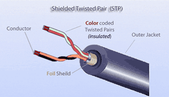
    Shielded Twisted Pair ( STP) cable is used less extensively for LANs compared to UTP cable because it is more expensive. STP is also composed of wire pairs covered with color-coded plastic insulation. STP cable can come with two wire pairs or four wire pairs like UTP.


    Speed: 10, 100 Mbps
      

    Maximum Distance:       100m
      

    Cost: expensive


    The difference between UTP and STP is that STP cable includes a foil shield covering the wire pairs which adds extra noise protection to the cable. Although the foil shield helps reduce noise, this extra shielding makes the wire more expensive and more difficult to install because the shield must be grounded.

    Although STP is used in LANs today and offers good protection from noise interference, UTP cable is still more commonly used.

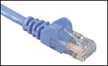
    RJ-45 connectors are used on the ends of UTP and STP cables

    A hub or switch must be used when creating a network with more then two nodes.


    Fiber-Optic

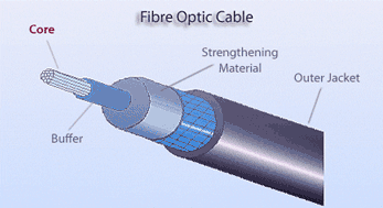
    Fiber optic cable is commonly used for high-bandwidth network backbones. A fiber cable is composed of an inner core, typically made of glass, through which light is transmitted. Surrounding the core is a cladding and buffer material which helps keep the light in the core and surrounding the buffer is a strengthening material which helps prevent stretching of the core. An outer jacket helps protect the cable from external damage.


    Speed:
         100 to over 10,000 Mbps
      

    Maximum Distance:      varies,
         up to 2 KM multimode
         over 10 KM single-mode.
      

    Cost:expensive


    Although it is expensive, fiber offers many advantages such as...

    • Noise resistance: - Fiber is not subject to electromagnetic interference (EMI) or radio frequency interference (RFI)
         
    • Resistant to Attenuation: - Fiber is subject to less signal attenuation than copper.
         
    • Cable Length : - Fiber can run for longer distances than copper media.
         
    • Security: - Fiber is more secure compared to copper and wireless media. Fiber cables are difficult to tap into unlike copper cables which generate electromagnetic fields.
         
    • Ease of installation : - Fiber is fairly easy to install.

    To understand fiber-optics you must first understand some of the properties of light. Light is part of the electromagnetic spectrum. Light energy is emitted from electrons when they change orbits and the energy travels in the form of a wave through a vacuum, air, water, glass and other materials.

    Light, radio, microwave, X-rays are all part of the electromagnetic spectrum.The different types of energy have different wave lengths. The wave length of light is in the kind of in the middle between ultra-violet (extremely short high-frequency waves) and infrared (long low-frequency waves.) Frequency and wavelength are directly related. The higher the frequency, the the shorter the wave length.

    Infrared or laser light is commonly used in fiber-optic cables. Infrared light has wave lengths slightly too long to be visible to the human eye.

    When an electromagnetic wave is generated, it travels in straight lines out from the source, in all directions. These lines are called light rays. When a light ray travels through a vacuum, it travels at a speed of 3000,000 metres per second. (This is fast, it takes a light ray about nine minutes to travel from the sun to the earth.)

    When a light ray hits surface, it slows down. How much it slows down, depends on the material. Some of the energy from the light ray may be reflected back from the material, some of the ray is absorbed. You can see yourself reflected in some materials such as glass, water and mirrors because part of the light rays reflect back to your eyes.

    The angle at which a light ray hits a surface is called the angle of incidence.

    The angle at which a light ray is reflected back is called the angle of reflection.

    Part of the light ray may travel into the material and it bends as it does so. The angle at which the ray travels into the material is called the angle of refraction. Different materials bend light to a different degree and the degree to which a material bends light is called its index of refraction. So, how much a light ray bends when it travels between two materials depends on the index of refraction of the both materials.
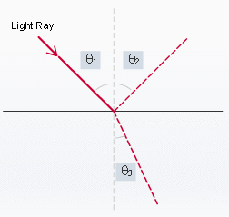


    Angle of Incidence
        

    Angle of Reflection
      

    Angle of Refraction

    If a light ray hits a material such as glass head on, with an angle 900 to the surface, the light ray travels directly into the material and no part is reflected back. A fiber-optic cable is designed to minimize refraction of light into the surrounding material, since this results in energy loss. This is the job of the buffer material that surrounds the core. The more like a mirror the buffer material is, the better, since any light ray that hits the buffer will be completely reflected back.

    There are two types of fiber-optic cable, multimode and single-mode fiber.

    Multimode fiber

    Multimode fiber allows light to travel different paths (modes) down the core. The path a light ray travels depends on the angle it is transmitted into the fiber core at the transceiver.

    Light rays travel different distances from the start to the end of the cable, depending on the angle at which they are transmitted, and the zigzag path followed. Since this would make different rays reach the destination at different times, a phenomenon called modal dispersion, a special type of glass core is used with a graded refraction index from the centre to the edge of the core. This accelerates light rays travelling near the edge of the core and slows down rays travelling toward the center of the core. Thus, light rays should reach the end of a cable at roughly the same time, regardless of modal dispersion.

    Infrared LEDs are usually used as the light source in multimode fiber installations.

    The diameter of multimode cables is typically 62.5 or 50 microns with an outer diameter of 125 microns. Fiber length can be up to 2000m.


    Multimode
    100/140
    Multimode
    50/125
    Multimode
    62.5/125

    Single-mode fiber

    Single-mode fiber, generally between eight and ten microns in diameter, can support higher data-transmission rates, as well as travel longer distances than multimode before needing a repeater. Single-mode fiber optic with laser sources is commonly used for high-speed, long-distance links.
                

      This higher speed is due to the smaller, single-mode core of 8 to 10 microns, much smaller than a multimode core which means light has far less room in which to bounce around.

    Also, the light source used is not LED but highly focused laser and the light rays are transmitted in a straight line right down the center of the core


    Single-mode
    10/125

    Single-mode fiber systems tend to be more expensive than multimode systems. This is primarily due to the fact that lasers are used as light sources in single-mode transceivers instead of LEDs, however, fiber lengths can reach up to 10 km.

    In general, fiber optic is more difficult to terminate than copper. Technicians have to ground down the ends to a properly focusing "lens," either onsite or at the manufacturing plant.
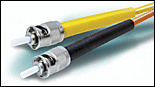


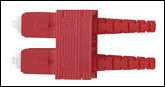
    SC connectors are used on the ends of multimode fiber-optic cables
     
    ST connectors are used on the ends of single-mode fiber-optic cables

    ~~Activity~~

     Activity A
    1. Try the flash card memory aid activity on Cables and Connectors
     

    Wireless


    Wireless technology has been around for years, used in radio, TV, satellite, mobile phones systems etc. However, wireless (WLAN) technology has expanded rapidly over the past few years and become much more viable for use by companies, mobile workers and home networks.

    Wireless networks are useful for allowing laptop computers or remote computers to connect to a LAN. Wireless networks are also useful where it is difficult or impossible to install cables.

    Wireless Signals

    Wireless technology uses electromagnetic signals transmitted as waves through air. Physical media such as copper or fiber cables is not required, which is one of the advantages.

    Radio, satellite, microwaves and wireless networks transmit electromagnetic waves using different frequencies and different wavelengths. The radio spectrum which is part of the electromagnetic spectrum uses frequencies ranging from 300 kHz to 300 GHz.

    Wireless networks transmit using two different frequency ranges:-

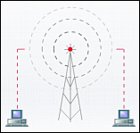
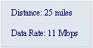
    • 2.4 GHz range - This is the frequency used for WLANs operating the 802.11b standard, the most commonly used WLAN standard. Data can be transmitted at a rate of 11Mbps.
          
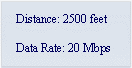
    • 5 GHz range - This frequency has recently become available for high-speed data transmission operating 802.11a standard. Data can be transmitted at a rate of over 20Mbps, up to 54Mbps at present.

    Unfortunately, although the 5 GHZ range can transmit data at higher rates than that of the 2.4 GHz range, its range is smaller.


    2.4 GHz Range
     
    5 GHz Range
     

    To convey information using radio waves you can use frequency modulation, amplitude modulation or phase modulation. For example, FM radio used frequency modulation and AM radio uses amplitude modulation.

    Whichever modulation technique is used, wireless signals are subject to noise interference from weather, EMI and RF emissions. Spread-spectrum modulation is a technique used to reduce signal noise. This techniques spreads a signal over a range of frequencies within the band in the hope that some frequencies will still get through in the case of any narrowband interference corrupting a specific frequency. FHSS and DSSS are two types of spread-spectrum technologies.

    • FHSS - Stands for frequency hopping spread spectrum. Transmissions hop from one frequency to another in a random way.
          
          
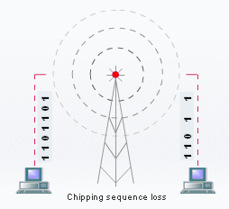
    • DSSS - Stands for direct sequence spread spectrum. Transmissions are send in a sequence called a chipping sequence. Even if a large percentage of the bits are lost at the receiving end, the data can still be reconstructed.

    Wireless Devices

    The devices used for wireless network communications are access points, wireless modems and wireless network cards.

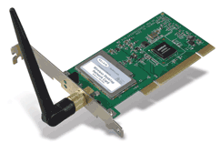
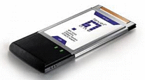
    Desktop computers and laptops use wireless network cards to transmit and receive wireless signals. The smallest WLAN you could build could consist of two workstations, each with a wireless network card. A peer-peer network could be set up between the workstations. When wireless network cards are operated in this fashion - directing communications between peers - the cards are said to operate in ad-hoc mode.


    The picture above shows a PCI wireless network card used in a desktop computer.
          
    The picture below shows a PCMCIA wireless card used in a laptop.
       

    More commonly, WLANS are set up where wireless signals are sent between workstations and a central device called an access point. This provides a central communication point, similar in concept to a star topology where a hub or switch provides a central communication point. This is called infrastructure mode.

    An access point can be wired into the physical LAN at one end and transmit signals to devices outside the physical boundaries of the cabled part of the LAN, thus extending the LAN. Typically, the radius of an access point is 100 to 500m, but the strength of a signal deteriorates with distance. Moreover, although signals can travel through some obstructions such as walls, the more surfaces there are between an access point and an end node the more the signal quality deteriorates.


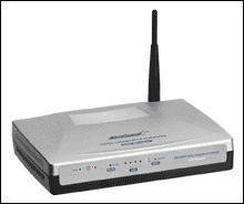
    Wireless ADSL-Modem
     
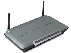
    Wireless Access Point

    Wireless LANs have several disadvantages. They only provide communication if the receiving device is not too far from the transmitter and the signal is not obstructed by too many obstructions. Another disadvantage is lack of security.

    Wireless Security

    Every access point on a WLAN has an SSID (service set identifier) number. When a device wants to join a WLAN, it either actively or passively scans the network.

    • Active scanning involves the scanning node actively looking for a WLAN with a specific SSID. On finding the required WLAN, the node issues a requests to join.
           
    • Passive scanning involves the node listening for management beacon signals sent by access points or wireless network cards in ad-hoc mode. The operating system usually lists all access points or ad-hoc network cards found. A node still has to issue a request to join.

    When a node attempts to join a WLAN, an authentication process is initiated. Two different methods of authentication include the open authentication system and the shared-key system.

    • Open system - In this system, access is allowed provided the connecting device uses the correct SSID. This is only used where security is not an issue, since anyone with a wireless card and appropriate wireless sniffing software can easily determine the SSID of an access point.
         
    • Shared-key system - In this system, the connecting device must know the SSID and also the WEP (wireless encryption privacy) key. WEP encryption uses a 64-bit or 128-bit encryption key. The access point is configured with a key and any device that wishes to authenticate must also know this key. Although this sounds secure, the algorithm is fairly simple and can be cracked.

    The 802.11 standard provides limited support for confidentiality through WEP. The fact that WEP contains flaws in the design that can allow eavesdropping of wireless data by sniffers means that additional measure have to be implemented to enhance security.

    Other security methods often implemented to prevent eavesdropping of signals include the use of VPNs ( virtual private networks) and EAP(extensible authentication protocol). In these systems, when a user attempts to authenticate to an access point, the access point passes the request along for additional authentication to a server, where the user must provide valid ID and password.

    A derivation of EAP developed by Cisco called LEAP (lightweight extensible authentication protocol) means that both the user and the access point must be authenticated to a network before access is allowed. This prevents the use of unauthorized access points.

    ~~Activity~~

     Activity B
    1. Try the flash card memory aid activity on Wireless Media
     

    Summary

    On completing these notes you should have learned the following key points:-

    • Coaxial cables were once commonly used on LANs.
    • Thicknet and thinnet are two grades of coaxial cable
    • BNC and T-connectors are used with coaxial cables
    • UTP and STP are two types of twisted pair media
    • UTP is the most commonly used cable on LANs today
    • UTP is subject to more noise interference than the other types of cables
    • RJ45 connectors are used with UTP cables
    • Fiber-optic cables offer high-bandwidth connections over long distances
    • Fiber is subject to less noise interference but is more expensive
    • Light signals are sent down fiber cables
    • Light signals obey the law of refraction and reflection
    • Multimode and single-mode are two types of fiber-optic cables
    • SC and ST connectors are used with fiber-optic cables
    • Wireless networks are useful for locations where it is difficult to install cables
    • Access points and wireless network cards are two devices used on wireless networks
    • WLANs use spread-spectrum technology to reduce noise interference
    • WEP is an encryption security method designed to protect wireless transmissions
    • Other security methods such as VPN, EAP and LEAP are used to supplement WEP and provide even more secure transmissions
    • Wireless signals can deteriorate with distance.


    Site Home

    Top

    Unit Home


    This Unit 

    Unit Information

    Assessment

    Syllabus

    Scheme of Work

    Learning Resources

    Notes & Lessons

    Assignments

    Quizzes

    Activities

    Resources

    Books & Things

    Links